System Components
RECEIVERS
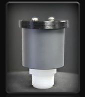
SHUT-OFF VALVES
RECEIVERS
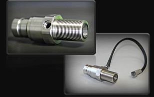
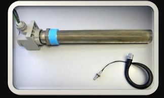
The Hartmann Receiver is uniquely designed to compensate for expansion due to fluid freezing and is the fill point for ground level fill. It is compatible only with the Hartmann DEF Nozzle. The non-standard interface prevents cross contamination with fuel, coolant, etc.
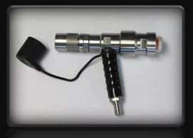
NOZZLE
SHUT-OFF VALVES
RECEIVERS
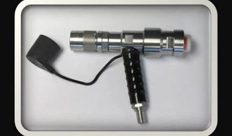
The unique interface of the Hartmann Nozzle connects only with the Hartmann DEF Receiver preventing introduction of the ammonia based DEF into other fast fill systems.
SHUT-OFF VALVES
SHUT-OFF VALVES
SHUT-OFF VALVES
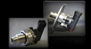
The Hartmann Shut-Off Valve prevents overfilling of DEF tanks and also communicates with the filling nozzle, allowing disconnection under pressure.
VENTS
BREATHER
SHUT-OFF VALVES
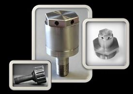
Hartmann DEF vents are to be mounted to the reservoir in order to exhaust air during the fill cycle.
BREATHER
BREATHER
BREATHER
Hartmann DEF Breathers can be mounted to reservoirs and are designed for bi-directional air flow during fill cycle (filtered inlet air).
HEATERS
BREATHER
BREATHER
These DEF compatible heaters are for in-tank or attached to Hartmann DEF components
DEF Fast Fill Fluid Control System
DEF Shut-Off Valves
DEF Nozzles
DEF Fast Fill Control System
DEF Receivers
DEF Fast Fill Control System
DEF Fast Fill Control System
DEF Fast Fill Control System
- Closed fill system prevents pressurizing DEF reservoirs
- DEF transfer closed system design eliminates external contamination
- The ability to connect and disconnect while supply line is pressurized
Standard Operating Procedure
DEF Fast Fill Control System
Standard Operating Procedure
- Energize supply pump
- Attach DEF Fill Nozzle to receiver
- Actuate Nozzle
- Shut-off valve opens and filling begins
- Displaced air escapes through vent
- Once the fluid level in the tank has reached the "full level", the fill level control signals the shut-off valve and nozzle to close
- No more DEF can be introduced into the reservoir
- Remove nozzle and the vehicle is ready for service
Key System Features
DEF Fast Fill Control System
Standard Operating Procedure
- Fill rates up to 800 LPM/200 GPM
- Positive shut-off prevents spillage and pressurizing of reservoir
- Fluid specific nozzle and receiver prevent cross contamination
- Remote vent prevents pressurization, allowing the use of think wall or molded reservoirs
- System tested to -40 degrees
- 100% DEF compatible materials and components
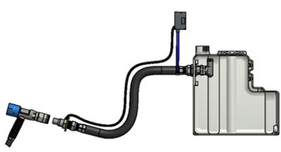
Hartmann Dri-Line™ Evacuation System
A self-contained fluid evacuation system for Tier IV Final engines using SCR to prevent fluid or DEF lines from freezing. Designed for off-road and heavy duty applications.
The Patent Granted Dri-Line™ Fill System was designed for fluid transfer applications where removing the fluid in a conduit is necessary due to freezing, reactivity, contamination, fluid value, or environmental safety concerns. The Dri-Line™ eliminates the need for costly drainage systems, heated hoses, heated couplings and receivers, and the power supplies, controllers, wiring, and other electronics to support these devices. The Dri-Line™ enables instantaneous filling upon startup. The Dri-Line™ system forces all fluid out of the conduit and into the reservoir, leaving only a trace of fluid that cannot impact future operations even if frozen. Evacuating the conduit typically recovers 99% of the fluid in the conduit and requires less than 1% of the energy needed in heated lines. The Dri-Line™ Ground Level Fill (GLF) was originally designed to deal with the complex issues of GLF of Diesel Exhaust Fluid (DEF) into construction and mining equipment.
KEY SYSTEM FEATURES
- Eliminates issues surrounding fluid line freezing
- Eliminates electrical energy required for heating hoses
- Provides instantaneous fill capability; no waiting for frozen fill systems to thaw
- Operates independent of on-vehicle CAN-BUS or other on-board control systems
Click here for Press Release